In the last post we got some life-signs from the FPGA onto the VGA display. The result was a display of some colored bars and a very fuzzy field of points.
Here I am trying to set up a "ROM" memory (modeled in the FPGA) that holds an image. I thought it would be good to plot a picture that we know what it is supposed to look like in order to spot if anything is not working as it should. So I located a screenshot from the old Wolfenstein 3d game. The image was 640x480 though, and the resolution I want to plot (for sentimental reasons) is 320x200 indexed graphics with a one byte color index per pixel. The screenshot had to be converted...
The FPGA board (Nexys A7-100T) has a 4 bit resistor ladder (DAC) per R,G and B channel for the VGA. This means that there are 16 different intensities possible for each color component or, in other words, 4096 colors possible in total. A one byte color index means that we can index 256 different colors from a palette made up of 256 color-intensity triplets of 4 bits (nibbles).
I did not find any out-of-the-box picture converter that would take the picture as input and output indexed color with nibble resolution per color. Gimp, however, lets you save an image as C source code! So that is what I did and then wrote a little bit of C code to convert that "image as C source" to the format I wanted. Gimp took care of most of the work by outputting an indexed image of 256 indices but where each R,G and B intensity in the palette had 8 bit resolution. My C program, very naively, just reduced the 8 bits down to 4. If you look at the photos of my VGA monitor below, the conversion to 4 bit per color channel takes place after screenshot 10 and the next (unnumbered) image has colors much more like the original. (of course given all this conversion (and even compressing file-formats involved intermediately, there are some artifacts in the final image).
I would like to extend thanks to some friends (that I wont mention by name here in case they wouldn't like that). While working on this I was posting intermediate pictures on FP and got lots of tips and feedback! Thanks guys (in case you stumble upon this and know who you are).
| 1 | 2 |
|---|---|
|
|
| 3 | 4 |
|---|---|
 |
 |
| 5 | 6 |
|---|---|
 |
 |
| 7 | 8 |
|---|---|
 |
 |
| 9 | 10 |
|---|---|
 |
 |
This post will cover two VHDL modules. One of the modules implement the memory and the other the display logic. The display logic part is similar to the previous post but with tweaks!
The memory module will be 64kb (64x1024 65536 bytes) and will store both the color indices of the picture and the nibbles that make up the palette. The interface to this memory will be an address, from 0 to 63999 and there will be 3 output signals of 4 bits each for R,G and B. So each access to memory will first look up the index, and than use that index to look up the appropriate nibbles to output onto the R,G and B channels.
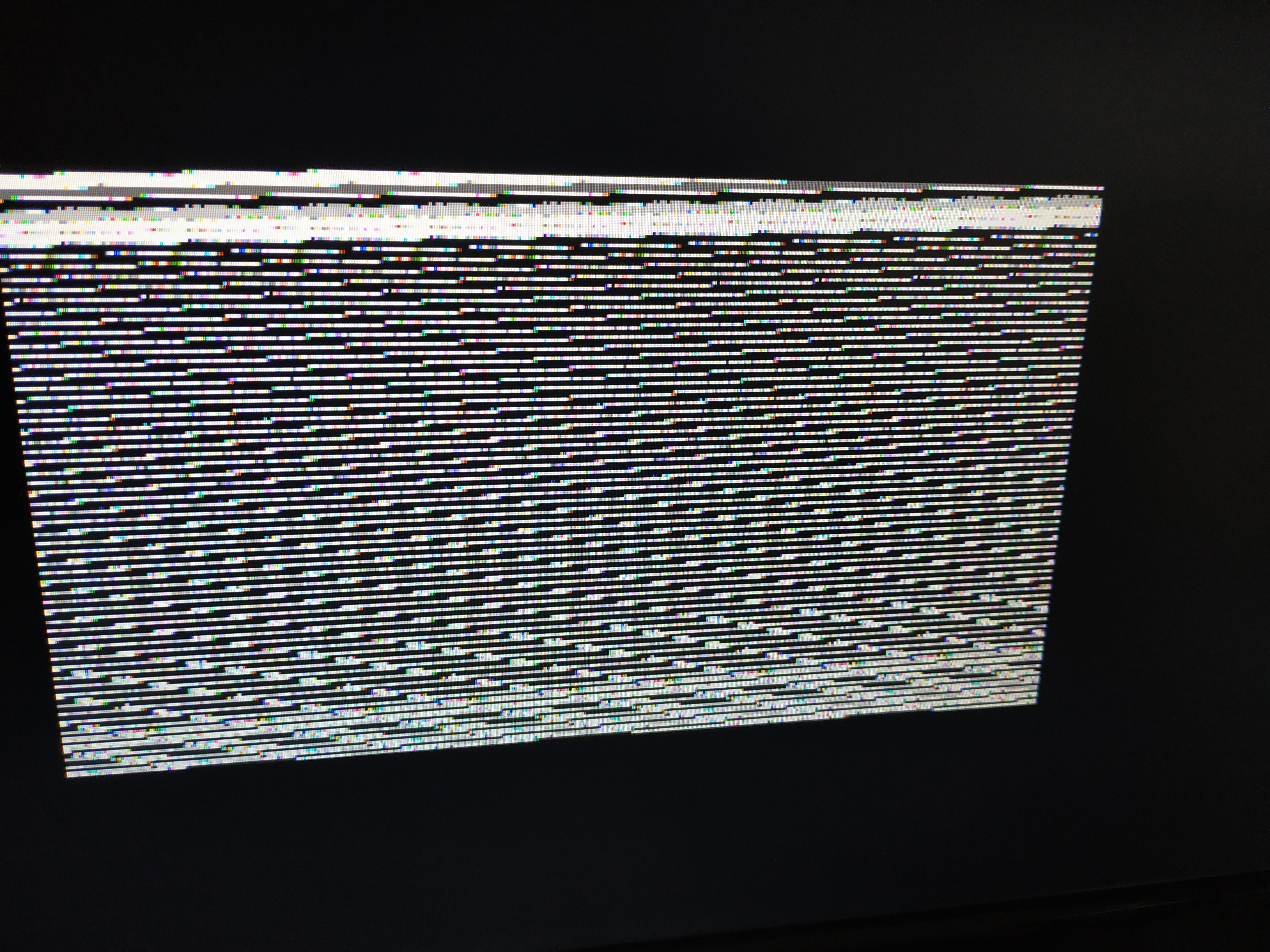
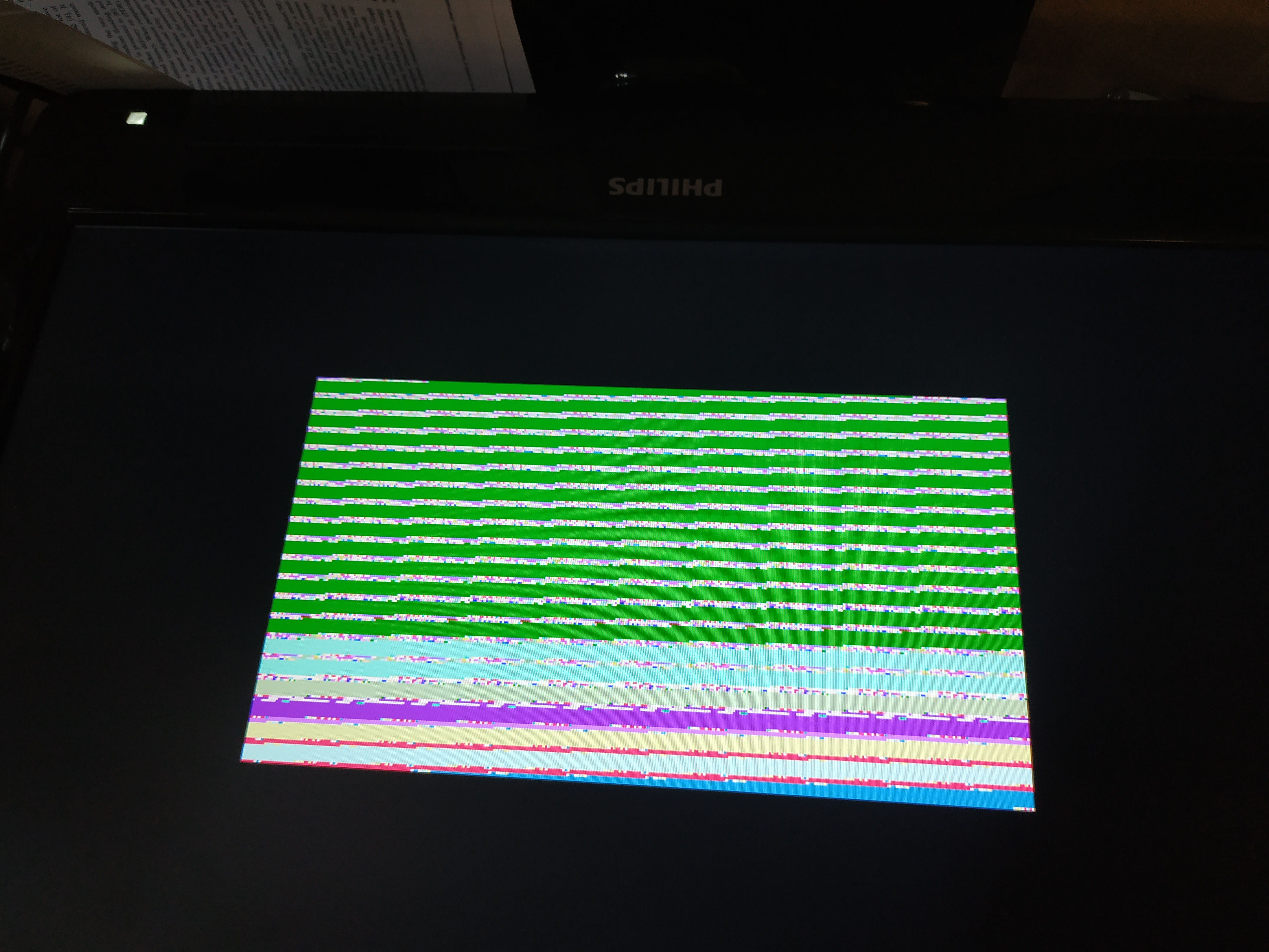
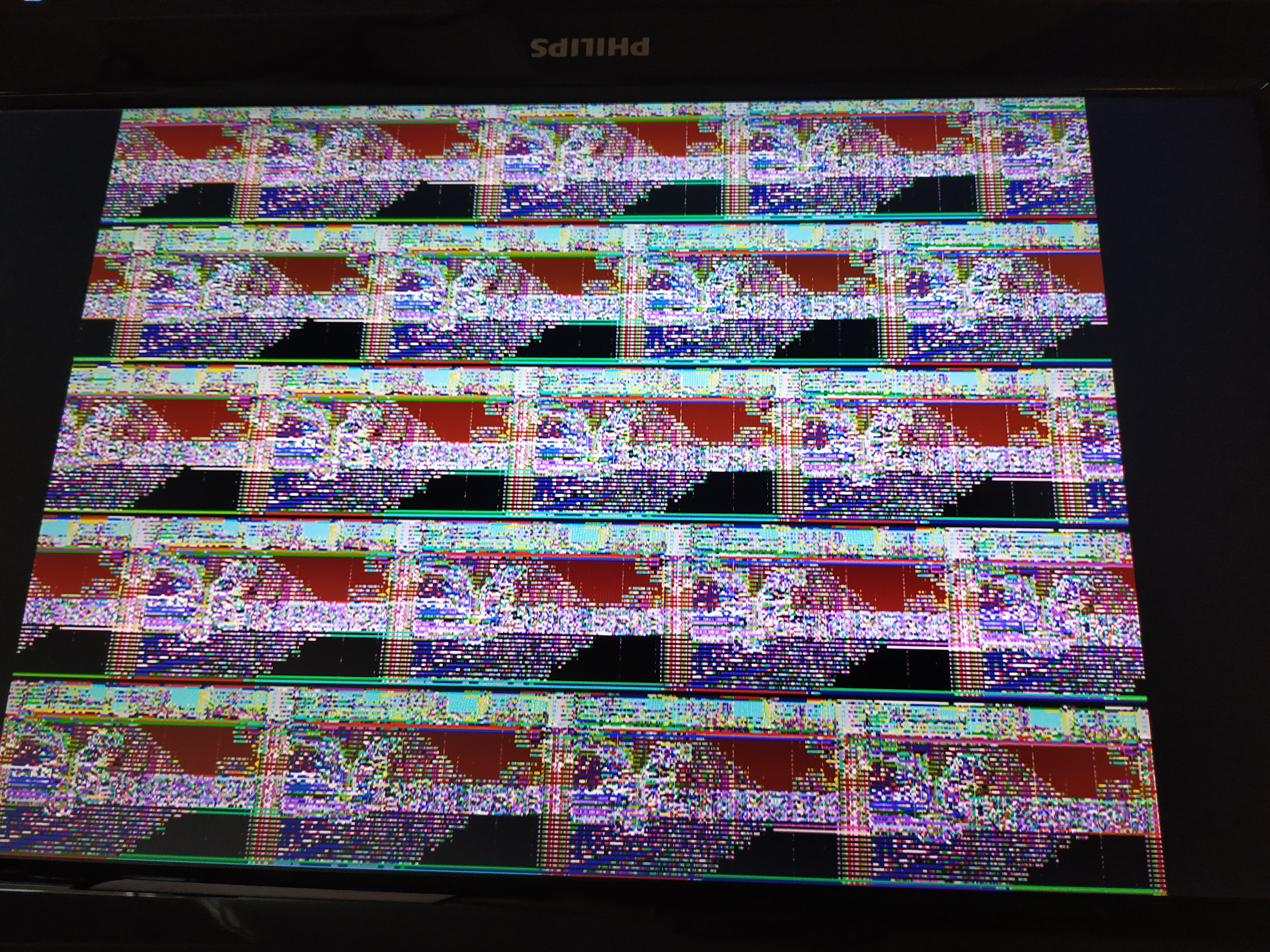
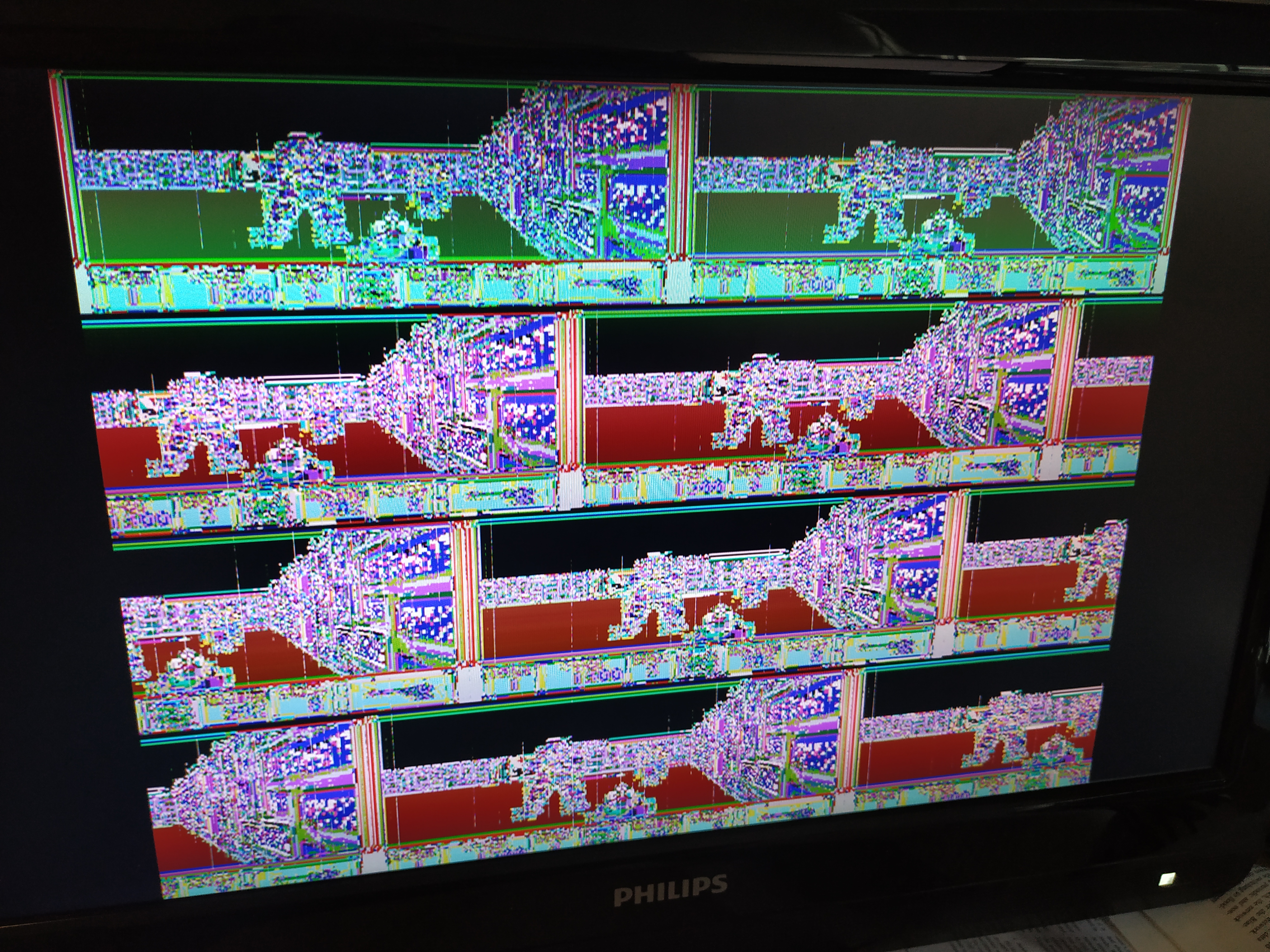
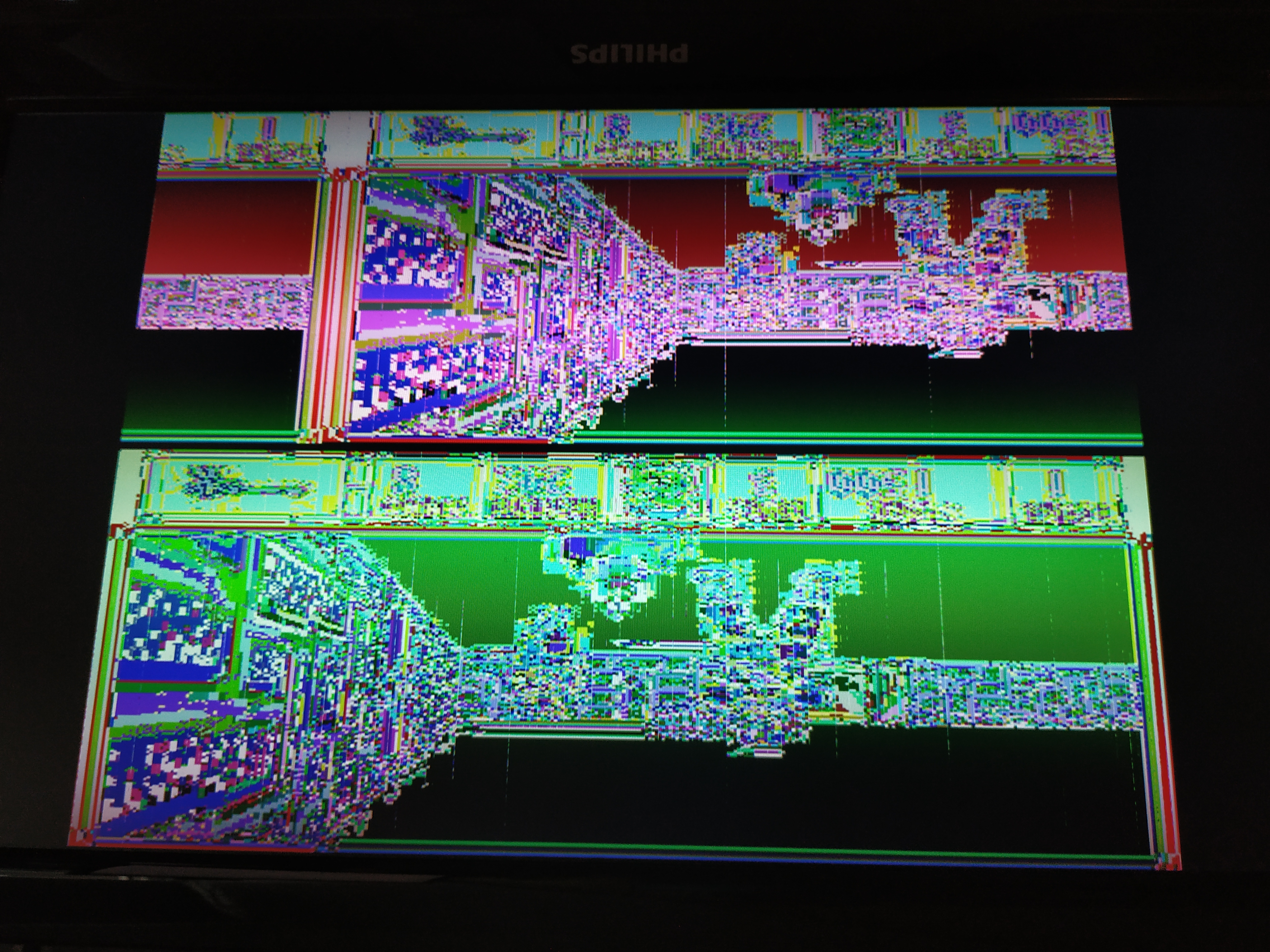
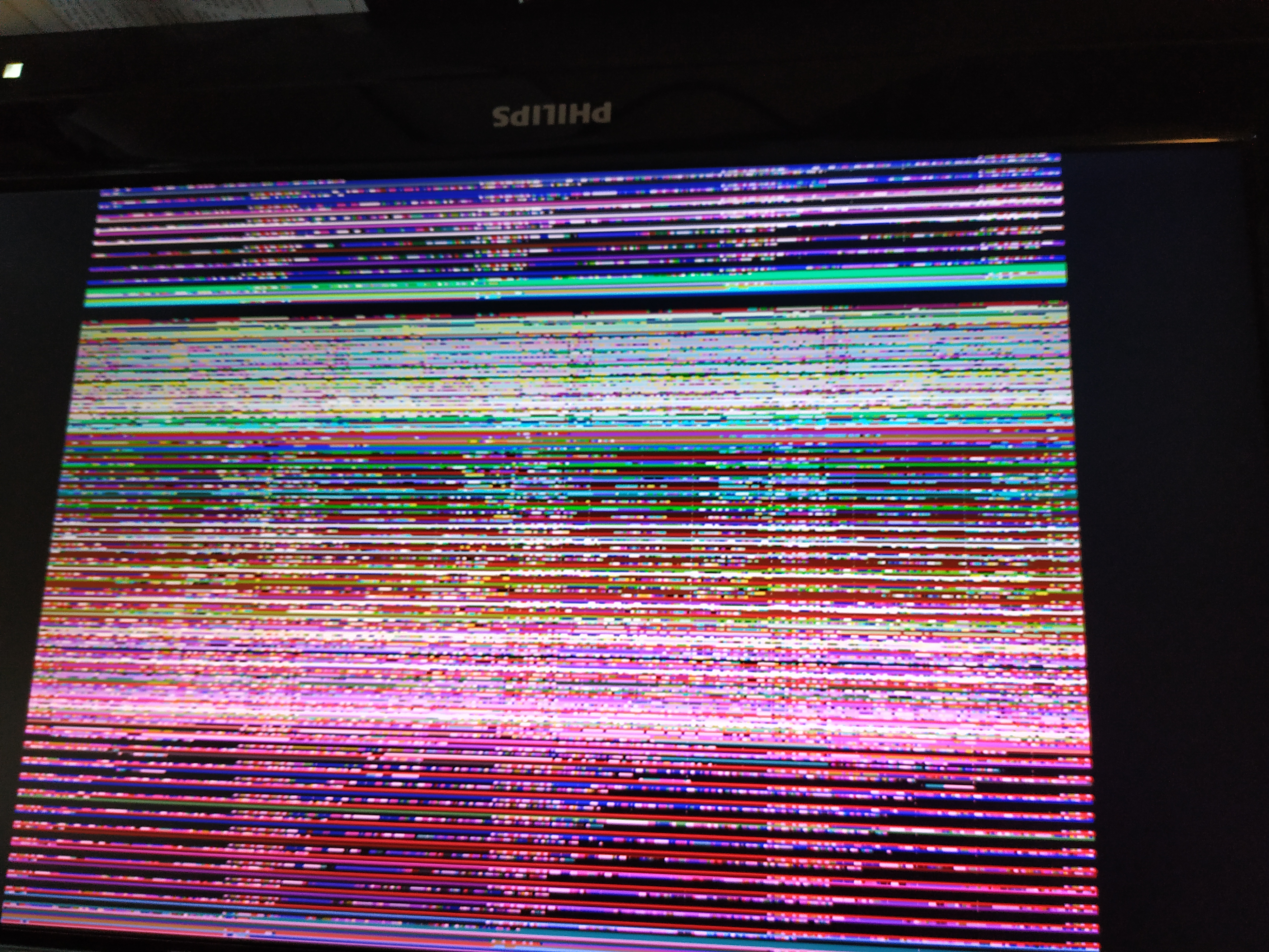
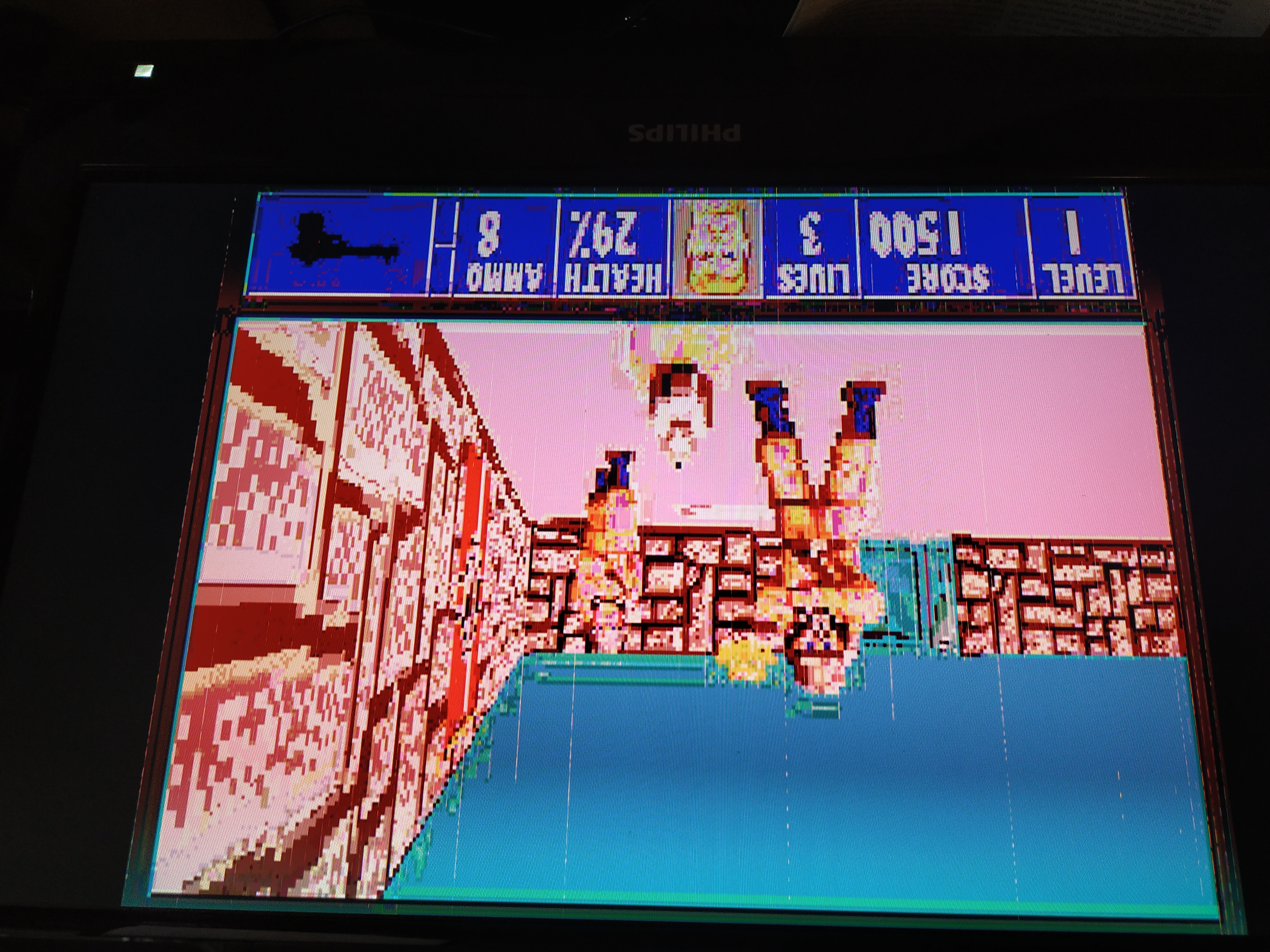
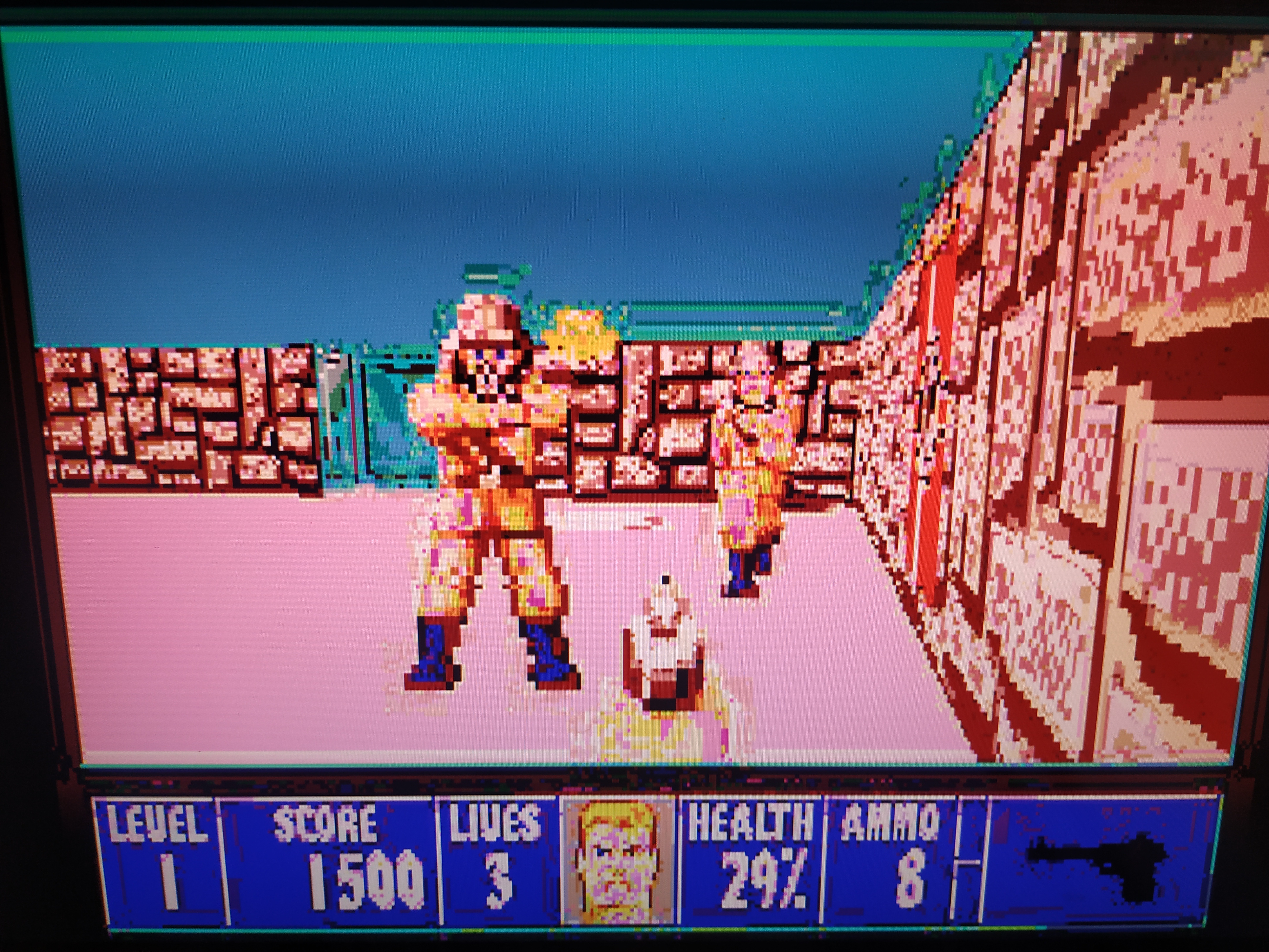
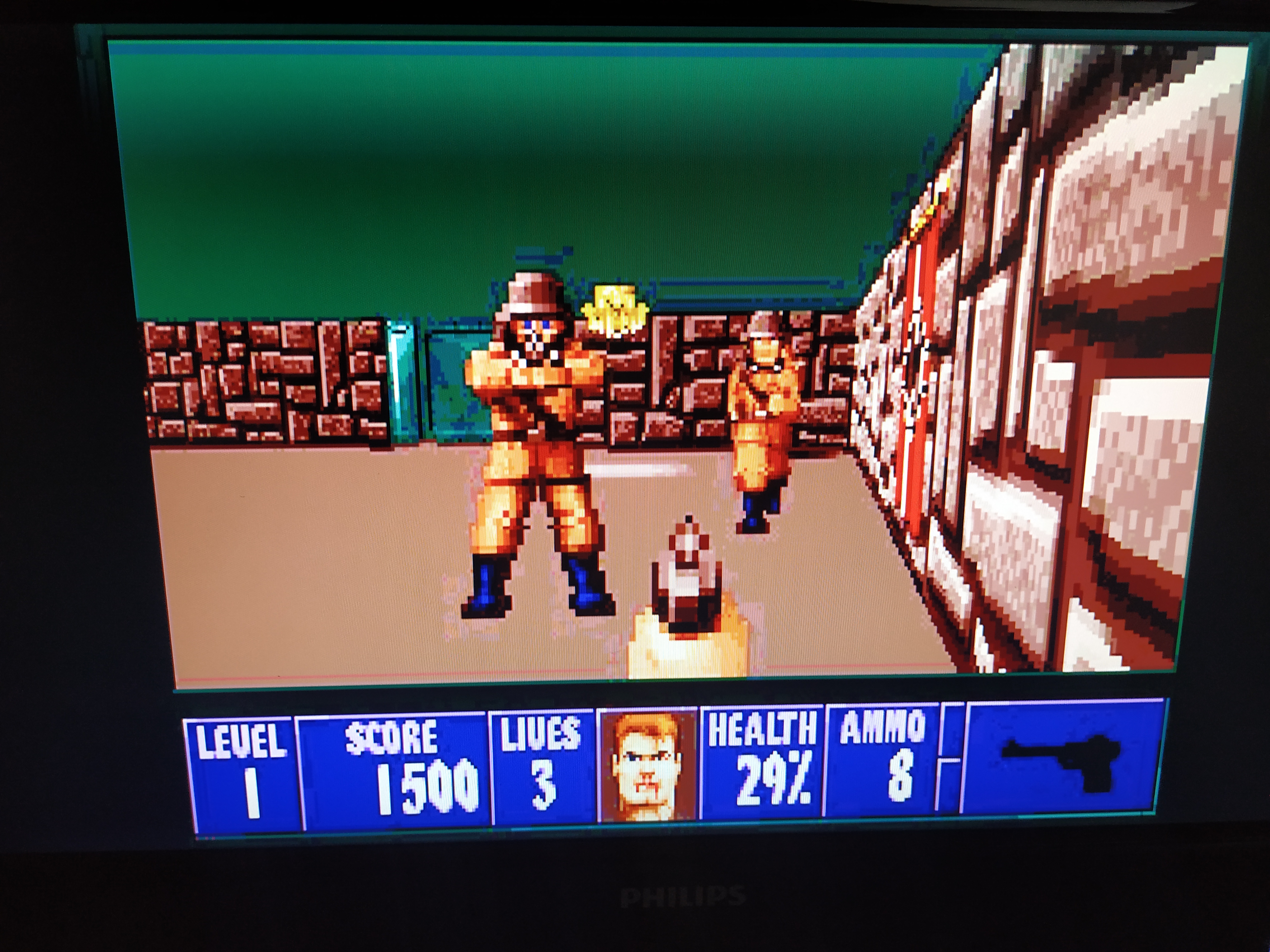
The pictures represent different stages along the implementation. The first two images (1 and 2) results from being way of in the calculation of what to read from memory. In pictures 3 and 4 we can see that the correct area of memory is being accessed but clearly not in the correct way. There is quite a bit going on there as the picture is 320x200 and the displayed resolution is 640x400, how on earth I managed to get 4 copies horizontally and 5 vertically is a mystery ;)
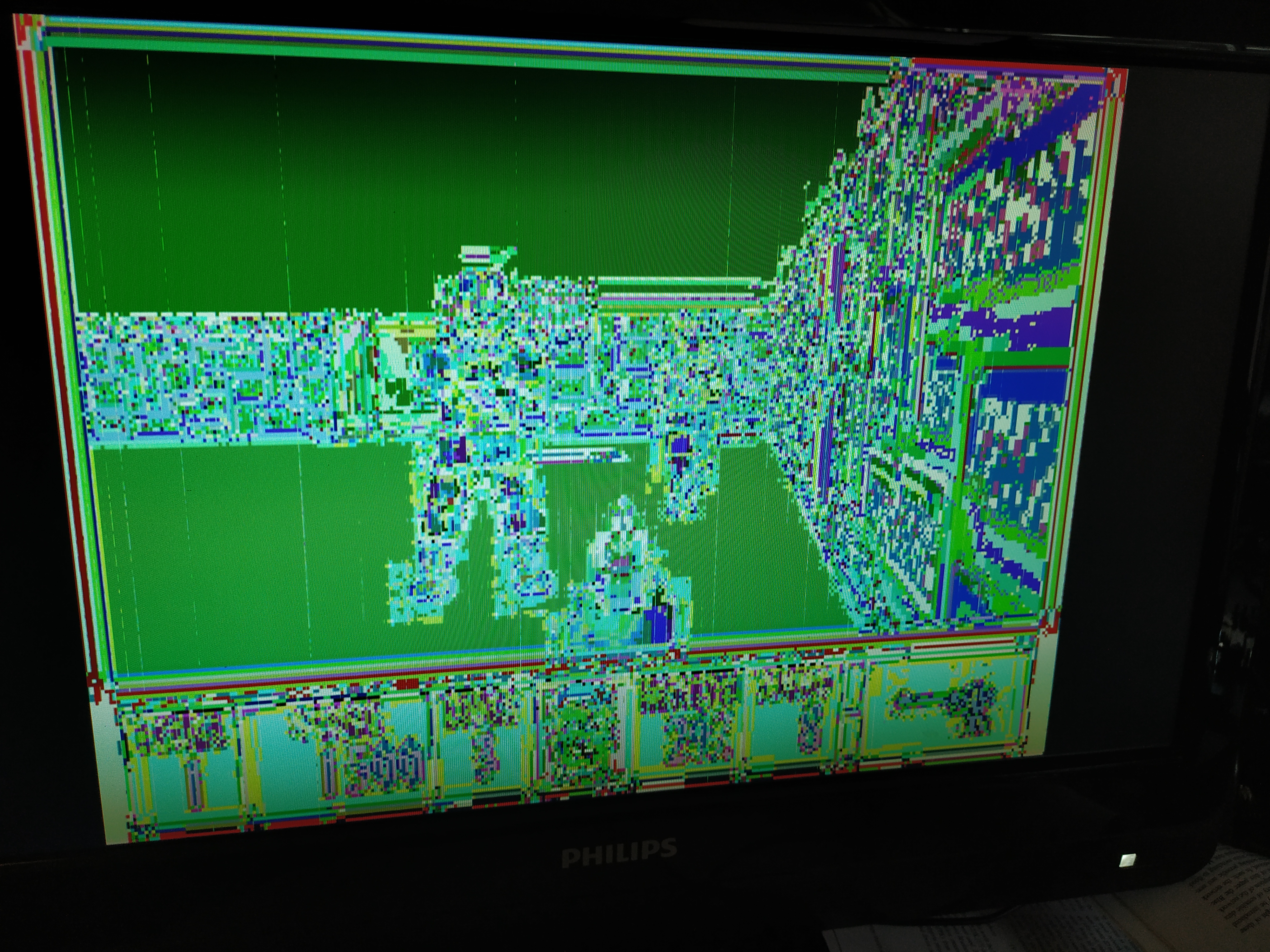
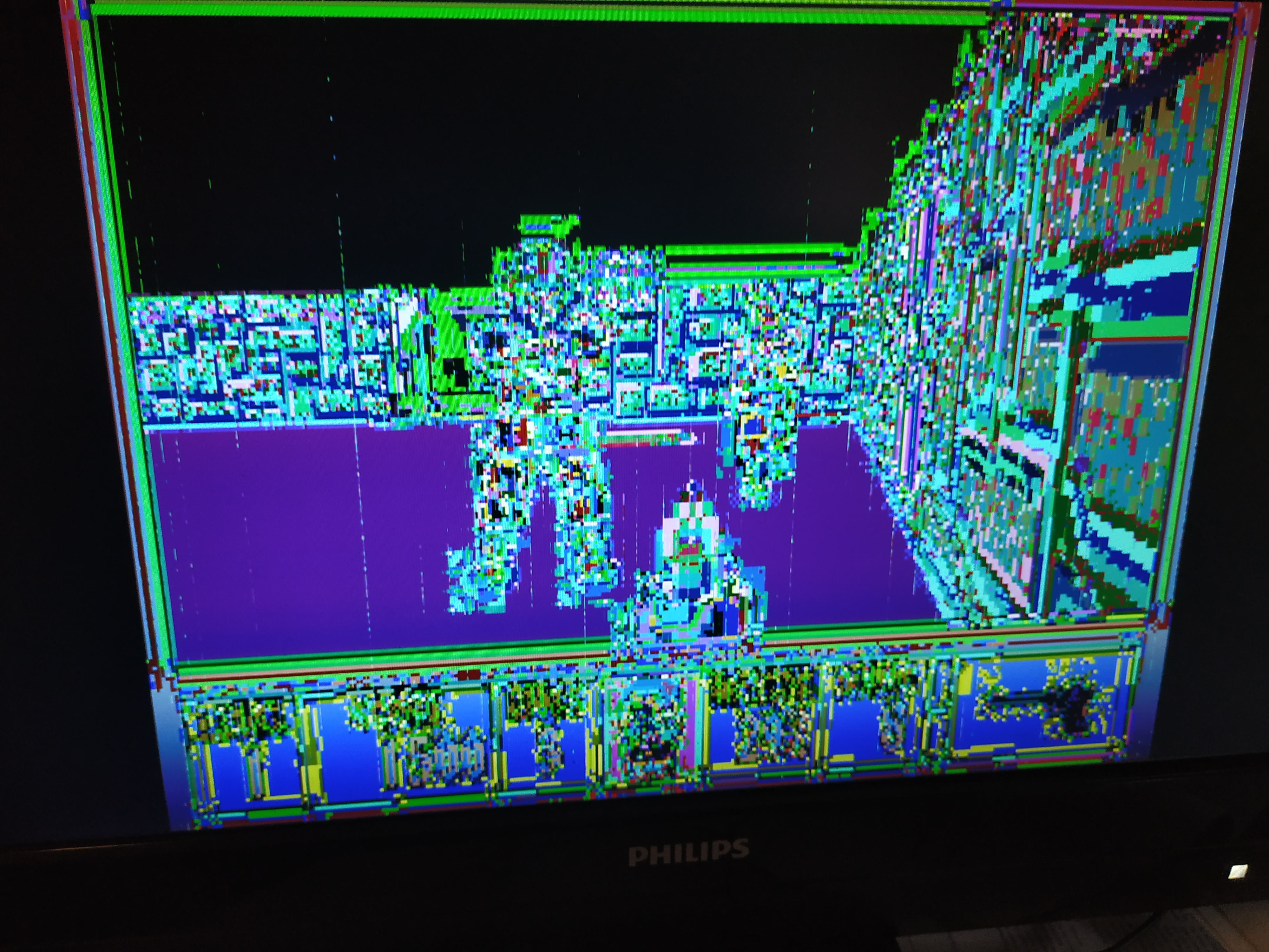
Eventually over a sequence of attempts the accesses and the scaling get better (with one out-lier picture 6, which was a clear mistake).
Pictures 7, 8 and 9 are starting to look really good. The picture is recognizable but the colors are a way off, so this must be something about the lookup of the R,G and B intensities.
The difference between picture 9 and 10 is interesting. In Pic 9 there are these vertical lines here and there and in 10 those are gone. The vertical lines disappeared when adding output "registers" for the R,G and B nibbles that will hold these values stable for the duration of a pixel-clock period.
The last picture is using more or less the same VHDL implementation as picture 10, but the image source data has been converted to a palette with 16 intensity levels per R,G and B channel.
The image converter C code includes a file called wolf.h which is generated using GIMP. The h-file defined two arrays, header_data_cmap (containing palette values) and header_data (containing the image as 8 bit indices).
The problem is that the palette is stored using 8 bits per R,G and B intensity and we want only 4. I could not find an off-the-shelf tool that stores pictures as indexed (8 bit index) into palette of 256 4x4x4 colors.
The C program does one more thing and that is to output the result after conversion as a string the binary representations of the values. This is a format that can be read into a memory in the VHDL code later.
The output of running this program looks like this:
...
11011101
11111101
10111111
11011100
11101110
11011101
11101111
11101110
11101111
11110011
11101110
...
The palette conversion function updates the header_data_cmap array in place. by looping over each index, converting each of the R,G and B values (between 0 and 255) to a double that is then divided by 16, rounded and stored back again into the array.
void convert_palette(void) {

  for (int i = 0; i < 256; i ++) {
    for (int j = 0; j < 3; j ++) {
      double c = (double)(unsigned char)header_data_cmap[i][j];
      c = c / 16.0;
      header_data_cmap[i][j] = (unsigned char)c;
    }
  }
}
There are two functions for printing as binary called print_binary and print_binary4. print_binary prints an 8 bit number and the "4" variant prints a nibble.
void print_binary(unsigned char a) {

  printf("%c%c%c%c%c%c%c%c\n",
     (a >> 7) & 1 ? '1' : '0',
     (a >> 6) & 1 ? '1' : '0',
     (a >> 5) & 1 ? '1' : '0',
     (a >> 4) & 1 ? '1' : '0',
     (a >> 3) & 1 ? '1' : '0',
     (a >> 2) & 1 ? '1' : '0',
     (a >> 1) & 1 ? '1' : '0',
     (a) & 1 ? '1' : '0');
}

void print_binary4(unsigned char a) {

  printf("%c%c%c%c",
     (a >> 3) & 1 ? '1' : '0',
     (a >> 2) & 1 ? '1' : '0',
     (a >> 1) & 1 ? '1' : '0',
     (a) & 1 ? '1' : '0');
}
In the main function, the palette is converted then the image indices are printed out as binary followed by lastly printing out the nibbles making up the palette.
void main(void) {

  convert_palette();


  for (int i = 0; i < 64000; i ++) {
    print_binary(header_data[i]);
  }

  int o = 0;
  for (int i = 0; i < 256; i ++) {
    for (int j = 0; j < 3; j ++) {
      print_binary4(header_data_cmap[i][j]);
      if (o == 1) {
    printf("\n");
    o = 0;
      } else {
    o += 1;
      }
    }
  }
}
The complete program listing looks like this:
#include <stdio.h>
#include <math.h>

#include "wolf.h"

void convert_palette(void) {

  for (int i = 0; i < 256; i ++) {
    for (int j = 0; j < 3; j ++) {
      double c = (double)(unsigned char)header_data_cmap[i][j];
      c = c / 16.0;
      header_data_cmap[i][j] = (unsigned char)c;
    }
  }
}

void print_binary(unsigned char a) {

  printf("%c%c%c%c%c%c%c%c\n",
     (a >> 7) & 1 ? '1' : '0',
     (a >> 6) & 1 ? '1' : '0',
     (a >> 5) & 1 ? '1' : '0',
     (a >> 4) & 1 ? '1' : '0',
     (a >> 3) & 1 ? '1' : '0',
     (a >> 2) & 1 ? '1' : '0',
     (a >> 1) & 1 ? '1' : '0',
     (a) & 1 ? '1' : '0');
}

void print_binary4(unsigned char a) {

  printf("%c%c%c%c",
     (a >> 3) & 1 ? '1' : '0',
     (a >> 2) & 1 ? '1' : '0',
     (a >> 1) & 1 ? '1' : '0',
     (a) & 1 ? '1' : '0');
}

void main(void) {

  convert_palette();


  for (int i = 0; i < 64000; i ++) {
    print_binary(header_data[i]);
  }

  int o = 0;
  for (int i = 0; i < 256; i ++) {
    for (int j = 0; j < 3; j ++) {
      print_binary4(header_data_cmap[i][j]);
      if (o == 1) {
    printf("\n");
    o = 0;
      } else {
    o += 1;
      }
    }
  }
}The memory, here called image_rom has three output signals called red, green and blue each of 4 bits. The inputs are clk and addr
The thought behind the memory is that you provide a value between 0 and 63999 (inclusive) as the address. The values < 64000 represent a valid pixel location on the screen such that values 0 - 319 is the topmost line of pixels, 320 - 639 is the next line and so on. So when a valid pixel "address" is provided, out comes its R,G and B intensities.
entity image_rom is
  Port (
    addr : in std_logic_vector (15 downto 0);
    red : out std_logic_vector (3 downto 0);
    green : out std_logic_vector (3 downto 0);
    blue : out std_logic_vector (3 downto 0);
    clk  : in std_logic
  );
end image_rom;
The memory type is defined to be an array of 64kb. This is more than enough room for the 64000 pixel indices and the 384 bytes (768 nibbles) of color intensity nibbles.
type MEM_ARRAY is ARRAY (0 to 65535) of std_logic_vector (7 downto 0);The contents of memory is initialized from a file. see for example this for more info.
impure function init_memory(fn : in string) return MEM_ARRAY is
    file f : text open read_mode is fn;
    variable ln : line;
    variable bv : bit_vector(7 downto 0);
    variable tmp_mem : MEM_ARRAY;
begin
    for i in MEM_ARRAY'range loop
        readline(f, ln);
        read(ln, bv);
        tmp_mem(i) := to_stdlogicvector(bv);
    end loop;
    return tmp_mem;
end function;
Then the mem signal, the actual memory, can be declared as follows.
signal mem : MEM_ARRAY := init_memory("memory.img");With that settled, we can take a look at the interesting part of the memory implementation, the read process. Here a lookup is done into memory using the address provided. The result of that lookup is an index into the palette which consist of nibble-triplets. The palette begins in memory on byte number 64000, or nibble number 128000, so this value is added to the index multiplied by 3. The index is multiplied by 3 because there is 3 nibbles per color.
Each RGB triplet is spread out across two consecutive bytes in a way that looks like this:
byte +0 +1     nibbles
0    rg br     0 - 3
2    gb rg     4 - 7
4    br gb     8 - 11
6    rg br     12 - 15
The byte (bytes) to access for a particular index is obtained by (index * 3) / 2 and (index * 3) / 2 + 1. Also note that depending on if the index is even or not you have two cases rg br if the LSB is 0 and br gb if the LSB is 1.
The result is code looking like this:
    read : process(clk)
        variable nibble_ix : unsigned(16 downto 0);
        variable b1 : std_logic_vector(7 downto 0);
        variable b2 : std_logic_vector(7 downto 0);
    begin
        if rising_edge(clk) then
            nibble_ix := to_unsigned(128000, 17) + unsigned(mem(to_integer(unsigned(addr))))*3;

            b1 := mem(to_integer( shift_right(nibble_ix, 1)(15 downto 0)));
            b2 := mem(to_integer( shift_right(nibble_ix, 1)(15 downto 0) + 1));

            -- 0 -> 0 1  rg br
            -- 1 -> 1 2  br gb
            -- 2 -> 3 4  rg br
            -- 3 -> 4 5  br gb
            -- 4 -> 6 7  rg br

            if (nibble_ix(0) = '1') then
                red <= b1(3 downto 0);
                green <= b2(7 downto 4);
                blue <= b2(3 downto 0);
            else
                red <= b1(7 downto 4);
                green <= b1(3 downto 0);
                blue <= b2(7 downto 4);
            end if;
        end if;
    end process;
I've added the complete listing for the memory implementation here:
library IEEE;
use IEEE.STD_LOGIC_1164.ALL;
use std.textio.ALL;
use IEEE.NUMERIC_STD.ALL;

entity image_rom is
  Port (
    addr : in std_logic_vector (15 downto 0);
    red : out std_logic_vector (3 downto 0);
    green : out std_logic_vector (3 downto 0);
    blue : out std_logic_vector (3 downto 0);
    clk  : in std_logic
  );
end image_rom;

architecture Behavioral of image_rom is

type MEM_ARRAY is ARRAY (0 to 65535) of std_logic_vector (7 downto 0);

impure function init_memory(fn : in string) return MEM_ARRAY is
    file f : text open read_mode is fn;
    variable ln : line;
    variable bv : bit_vector(7 downto 0);
    variable tmp_mem : MEM_ARRAY;
begin
    for i in MEM_ARRAY'range loop
        readline(f, ln);
        read(ln, bv);
        tmp_mem(i) := to_stdlogicvector(bv);
    end loop;
    return tmp_mem;
end function;

signal mem : MEM_ARRAY := init_memory("memory.img");

begin

    read : process(clk)
        variable nibble_ix : unsigned(16 downto 0);
        variable b1 : std_logic_vector(7 downto 0);
        variable b2 : std_logic_vector(7 downto 0);
    begin
        if rising_edge(clk) then
            nibble_ix := to_unsigned(128000, 17) + unsigned(mem(to_integer(unsigned(addr))))*3;

            b1 := mem(to_integer( shift_right(nibble_ix, 1)(15 downto 0)));
            b2 := mem(to_integer( shift_right(nibble_ix, 1)(15 downto 0) + 1));

            -- 0 -> 0 1  rg br
            -- 1 -> 1 2  br gb
            -- 2 -> 3 4  rg br
            -- 3 -> 4 5  br gb
            -- 4 -> 6 7  rg br

            if (nibble_ix(0) = '1') then
                red <= b1(3 downto 0);
                green <= b2(7 downto 4);
                blue <= b2(3 downto 0);
            else
                red <= b1(7 downto 4);
                green <= b1(3 downto 0);
                blue <= b2(7 downto 4);
            end if;
        end if;
    end process;
end Behavioral;The vga entity is unchanged compared to the last post
entity vga is
    Port (
        vga_r : out std_logic_vector(3 downto 0);
        vga_g : out std_logic_vector(3 downto 0);
        vga_b : out std_logic_vector(3 downto 0);
        vga_hs : out std_logic;
        vga_vs : out std_logic;

        clk : in std_logic;
        reset : in std_logic

       -- clk_out : out std_logic;
       -- hcnt : out unsigned(10 downto 0);
       -- vcnt : out unsigned(10 downto 0)
    );
end vga;
When in comes to the architecture there are also a bunch of things that are unchanged compared to last post. Focus here will what is new, but the entire VHDL code listing will be included at the end.
A new counter is added to keep track of which pixel value to fetch.
signal index_cnt : unsigned(15 downto 0);Then a couple of signals are added that are going to be connected to the memory.
    signal r : std_logic_vector (3 downto 0);
    signal g : std_logic_vector (3 downto 0);
    signal b : std_logic_vector (3 downto 0);

    signal img_addr : std_logic_vector (15 downto 0);
The memory is instantiated:
    image_mem : entity work.image_rom port map (
        addr => img_addr,
        red => r,
        green => g,
        blue => b,
        clk => pix_clock
    );
The clock division processes are exactly the same as in the last post and left out from here.
The index_cnt signal is fed as address to the memory.
img_addr <= std_logic_vector(index_cnt);Then there is a process for accessing the memory and keeping the R,G and B signals steady for a period of the clock. This is what fixed the vertical lines in the displayed image between picture 9 and 10 in the beginning of this text.
    output_reg : process(pix_clock)
    begin
        if rising_edge(pix_clock) then
            if (index_cnt < 64000) then
                vga_r <= r;
                vga_g <= g;
                vga_b <= b;
            else
                vga_r <= "0000";
                vga_g <= "0000";
                vga_b <= "0000";
            end if;
        end if;
    end process;
The rest of the timing logic takes place in a process called cnt_proc. This process cycles the h_cnt and v_cnt counters over their ranges and correspondingly also increments the index_cnt while in the valid display range of the h_cnt and v_cnt counters. Since the mode displayed is really 640x400 but the image resolution is 320x200, index_cnt is only incremented every other horizontal pixel and every other time we v_cnt we subtract an entire line from index_cnt leading to a duplication of pixel in H and V direction.
    cnt_proc : process(pix_clock, reset)
    begin
        if (reset = '1') then
            h_cnt <= to_unsigned(0, h_cnt'length);
            v_cnt <= to_unsigned(0, v_cnt'length);
            index_cnt <= to_unsigned(0, index_cnt'length);
        elsif rising_edge(pix_clock) then

            if (h_cnt < 800) then
                h_cnt <= h_cnt + 1;
                if (h_cnt < 640 and v_cnt < 400 and h_cnt(0) = '1') then
                    index_cnt <= index_cnt + 1;
                end if;
            else
                h_cnt <= to_unsigned(0, h_cnt'length);
                if (v_cnt < 449) then
                    v_cnt <= v_cnt + 1;
                    if (v_cnt < 400 and v_cnt(0) = '1') then
                        index_cnt <= index_cnt - 320;
                    end if;
                else
                    v_cnt <= to_unsigned(0, v_cnt'length);
                    index_cnt <= to_unsigned(0, index_cnt'length);
                end if;
            end if;
        end if;
    end process;
And that is it. The cnt_proc is quite messy and probably there are mistakes. One thing about getting visual feedback on stuff is that some bugs should have visible effects on the display. Say we were off by one in horizontal counting of the index_cnt, my guess is that this would lead to skewed image?!
Lastly, the entire VHDL listing for the implementation of the VGA architecture.
architecture Behavioral of vga is

    signal pix_clock : std_logic;
    signal clk_2 : std_logic;

    signal h_cnt : unsigned(9 downto 0);
    signal v_cnt : unsigned(9 downto 0);
    signal index_cnt : unsigned(15 downto 0);

    signal r : std_logic_vector (3 downto 0);
    signal g : std_logic_vector (3 downto 0);
    signal b : std_logic_vector (3 downto 0);

    signal img_addr : std_logic_vector (15 downto 0);

begin

    image_mem : entity work.image_rom port map (
        addr => img_addr,
        red => r,
        green => g,
        blue => b,
        clk => pix_clock
    );

    --clk_out <= pix_clock;
    --hcnt <= h_cnt;
    --vcnt <= v_cnt;

    clk_div_2: process(clk, reset)
    begin
        if rising_edge(clk) then
            clk_2 <= not clk_2;
        end if;
    end process;

    pix_clk_gen: process(clk_2, reset)
    begin
        if rising_edge(clk_2) then
            pix_clock <= not pix_clock;
        end if;
    end process;

    vga_hs <= '0' when h_cnt > 656 and h_cnt < 752 else '1';
    vga_vs <= '1' when v_cnt = 412 or v_cnt = 413 else '0';


    img_addr <= std_logic_vector(index_cnt);


    output_reg : process(pix_clock)
    begin
        if rising_edge(pix_clock) then
            if (index_cnt < 64000) then
                vga_r <= r;
                vga_g <= g;
                vga_b <= b;
            else
                vga_r <= "0000";
                vga_g <= "0000";
                vga_b <= "0000";
            end if;
        end if;
    end process;


    cnt_proc : process(pix_clock, reset)
    begin
        if (reset = '1') then
            h_cnt <= to_unsigned(0, h_cnt'length);
            v_cnt <= to_unsigned(0, v_cnt'length);
            index_cnt <= to_unsigned(0, index_cnt'length);
        elsif rising_edge(pix_clock) then

            if (h_cnt < 800) then
                h_cnt <= h_cnt + 1;
                if (h_cnt < 640 and v_cnt < 400 and h_cnt(0) = '1') then
                    index_cnt <= index_cnt + 1;
                end if;
            else
                h_cnt <= to_unsigned(0, h_cnt'length);
                if (v_cnt < 449) then
                    v_cnt <= v_cnt + 1;
                    if (v_cnt < 400 and v_cnt(0) = '1') then
                        index_cnt <= index_cnt - 320;
                    end if;
                else
                    v_cnt <= to_unsigned(0, v_cnt'length);
                    index_cnt <= to_unsigned(0, index_cnt'length);
                end if;
            end if;
        end if;
    end process;

end Behavioral;The 320x200 resolution is DOS-era nostalgia of course, the good old mode 13h. The "mode 13h" graphics mode was easy to work with as it had a linear 64000 bytes oh graphics memory. To write a pixel you just calculated how many bytes into this 64000 byte area the corresponding color index byte is located and change the value there. To set a pixel at pos (x,y) you computed (x * 320 + y) then added this to the base address, 0xA0000000, (the location in the address space where the VGA adapters memory was mapped to) and you had a pointer to your pixels color value.
Working with nibbles is a bit messy. I think the next step will be to implement a dual-ported "nibble" memory so that one port would have an 8 bit data bus and the other a 4 bit data bus. When writing a byte to this memory on the 8bit data-bus the most significant 4 bits will be thrown away and only the low nibble stored. That memory does not need to be large, it only needs to hold 256 * 3 nibbles, that is 384 bytes. With a specialized memory for the nibbles of color channel info, the lookup of color channel data should be a lot easier. We'll see if that works out.
Thanks for reading! If you have feedback, please send me an email or join the google group. I am not an FPGA expert and what I am writing about is my learning experience, so all hints and tips are much appreciated.
Please contact me with questions, suggestions or feedback at blog (dot) joel (dot) svensson (at) gmail (dot) com or join the google group .
© Copyright 2020 Bo Joel Svensson
This page was generated using Pandoc.