 .
.I want to try and make a memory module in VHDL. I have a vague long term plan but will keep that to myself at the moment, just in case it all goes into the bin.
I am not an VHDL expert and would love your feedback. Either send it to me in email or join the Google group associated with the blog.
It is very likely that later when we try to integrate the memory developed here into something larger, it will need to be tweaked or "fixed" if broken.
I want a memory that can go onto an 8bit data bus together with other things on that same bus. So the memory module must be able to make the data signals Float (to be not connected (high impedance)). The memory module should support both reading and writing, both operations taking place on the same data bus. There should be an enable signal to module so that we can chose to enable it or something else connected to the bus.
The size of the memory will be set by a generic parameter but the word-length will be fixed at a byte to start with.
So given the above, the entity declaration for the memory looks like this:
entity mem_8bit_single_port is
   generic (
        ADDRESS_BITS : integer := 16
    );
    Port (
        data : inout std_logic_vector(7 downto 0);
        addr : in std_logic_vector(ADDRESS_BITS-1 downto 0);
        ce : in std_logic;
        we : in std_logic;
        re : in std_logic;

        reset : in std_logic;
        clk: in std_logic
        );
end mem_8bit_single_port;
data is the data-bus of bytes and addr is the address-bus which is set to 16bits by default but is a generic parameter that can be customized. ce, we and re are the chip-enable, write-enable and read-enable signals. I am not entirely sure what to do with the reset signal at the moment.
So the idea is that to read from the memory you put an address on the address-bus, enable ce and re and the result should arrive on data. For storing, you put an address on the address-bus, enable ce and we. If both we and re are enabled, then one of those operations will take priority over the other. Which one is given priority depends on the implementation.
The implementation of the memory is based on an array of 8-bit std_logic_vector defined by this type:
    type mem_array is array((2**ADDRESS_BITS)-1 downto 0) of
        std_logic_vector(7 downto 0);
The number of elements in the array is decided by the number of address bits. We need a couple of signals internally in the architecture. These are mem, the actual instance of an object of type mem_array and we need a kind of intermediate signal that I call data_out. I ran into some problems here at first trying to implement the memory without the intermediate data_out signal.
The problem I ran into is that you want to put the data signals into state Z whenever there is no ce. I thought it would be fine to this with a statement like this:
data <= "ZZZZZZZZ"; in the architecture. The plan was then to, later, in a process override that setting with actual data if needed. But that is not possible it seems. The statement, as I understand it right now should mean something like data is always "ZZZ..." and what happens then if I later have a (inside a process) data <= the_actual_data is that data is being driven from two places at once. So, do not do that...
Here is what a better statement looks like:
data <= data_out when (ce = '1' and re ='1' and we = '0') else "ZZZZZZZZ";and this is where the intermediate data_out signal comes in. The data_out signal is given a value within a process that is sensitive to the clk signal.
    process(clk, reset)
    begin
        if (reset = '1') then
            data <= "ZZZZZZZZ";
        elsif rising_edge(clk) then
            if (ce = '1' and re = '1') then
                data_out <= mem(to_integer(unsigned(addr)));
            elsif (ce = '1' and we = '1') then
                mem(to_integer(unsigned(addr))) <= data;
            end if;
        end if;
    end process;
This process check the state of ce, we and re and either decides to put a value from the memory onto the data-bus or take the value from the data-bus and place it in memory.
I am not actually sure what to do about the reset signal. It just feels nice and uniform that there is one. So right now reset just disconnects the memory from the bus, for the duration of the reset.
Here is the full VHDL listing for the memory module:
library IEEE;
use IEEE.STD_LOGIC_1164.ALL;
use IEEE.NUMERIC_STD.ALL;

entity mem_8bit_single_port is
    generic (
        ADDRESS_BITS : integer := 16
    );
    Port (
        data : inout std_logic_vector(7 downto 0);
        addr : in std_logic_vector(ADDRESS_BITS-1 downto 0);
        ce : in std_logic;
        we : in std_logic;
        re : in std_logic;

        reset : in std_logic;
        clk: in std_logic
        );
end mem_8bit_single_port;

architecture Behavioral of mem_8bit_single_port is

    type mem_array is array((2**ADDRESS_BITS)-1 downto 0) of
        std_logic_vector(7 downto 0);

    signal mem : mem_array;
    signal data_out : std_logic_vector(7 downto 0);
begin

    data <= data_out when (ce = '1' and re ='1' and we = '0') else "ZZZZZZZZ";

    process(clk, reset)
    begin
        if (reset = '1') then
            data <= "ZZZZZZZZ";
        elsif rising_edge(clk) then
            if (ce = '1' and re = '1') then
                data_out <= mem(to_integer(unsigned(addr)));
            elsif (ce = '1' and we = '1') then
                mem(to_integer(unsigned(addr))) <= data;
            end if;
        end if;
    end process;
end Behavioral;This will be more like manual inspection so far as I am not putting any assertions into the testbench.
I define signals in the testbench to hook up to the memory in order to feed it with stimuli.
    signal tb_data : std_logic_vector(7 downto 0);
    signal tb_addr : std_logic_vector(15 downto 0);
    signal tb_we : std_logic := '0';
    signal tb_re : std_logic := '0';
    signal tb_ce : std_logic := '1';

    signal tb_clk : std_logic := '0';
    signal tb_reset :std_logic := '0';
And we need to map the testbench signals to the corresponding memory signal.
m : entity work.mem_8bit_single_port
    port map
    (
        reset => tb_reset,
        clk => tb_clk,
        we => tb_we,
        re => tb_re,
        ce => tb_ce,
        addr => tb_addr,
        data => tb_data
    );
And set up a clock.
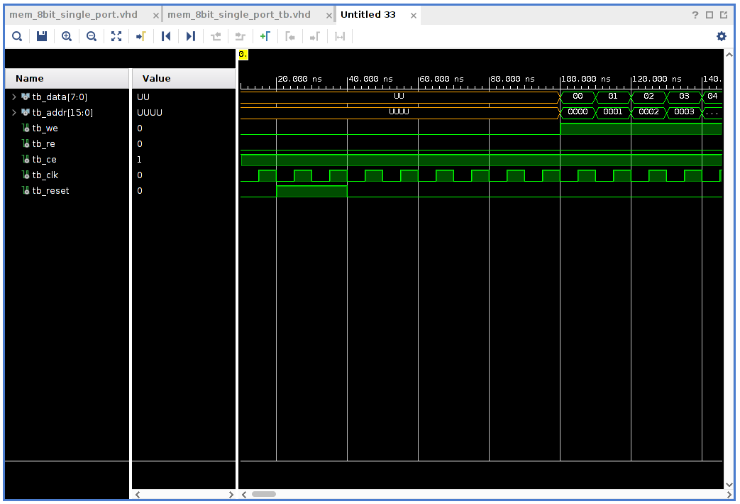
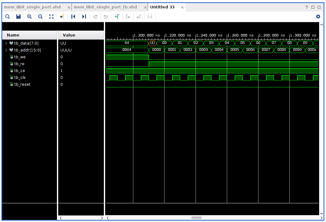
tb_clk <= not tb_clk after 5ns;The rest of the testbench is made up from a process that first of all resets the memory. Then executes a loop that performs a bunch of writes into the memory. This is followed by another loop that performs a bunch of reads from the memory.
   tb_proc : process
    begin

        wait for 20ns;
        tb_reset <= '1';
        wait for 20ns;
        tb_reset <= '0';

        wait for 60ns;

        tb_we <= '1';
        tb_re <= '0';
        tb_ce <= '1';
        for i in 0 to 100 loop

            tb_addr <= std_logic_vector(to_unsigned(i, 16));
            tb_data <= std_logic_vector(to_unsigned(i, 8));


            wait for 10ns;
        end loop;

        wait for 100ns;
        tb_data <= "ZZZZZZZZ";
        tb_we <= '0';
        tb_re <= '1';
        tb_ce <= '1';
        for i in 0 to 100 loop

            tb_addr <= std_logic_vector(to_unsigned(i, 16));

            wait for 10ns;
        end loop;

        wait;
    end process;
If you are not familiar with how to create a testbench (simulation source) in Vivado, have a look at this post.
Here is the complete testbench code listing:
library IEEE;
use IEEE.STD_LOGIC_1164.ALL;
use IEEE.NUMERIC_STD.ALL;

entity mem_8bit_single_port_tb is
end mem_8bit_single_port_tb;

architecture Behavioral of mem_8bit_single_port_tb is

    signal tb_data : std_logic_vector(7 downto 0);
    signal tb_addr : std_logic_vector(15 downto 0);
    signal tb_we : std_logic := '0';
    signal tb_re : std_logic := '0';
    signal tb_ce : std_logic := '1';

    signal tb_clk : std_logic := '0';
    signal tb_reset :std_logic := '0';

begin

m : entity work.mem_8bit_single_port
    port map
    (
        reset => tb_reset,
        clk => tb_clk,
        we => tb_we,
        re => tb_re,
        ce => tb_ce,
        addr => tb_addr,
        data => tb_data
    );


tb_clk <= not tb_clk after 5ns;

    tb_proc : process
    begin

        wait for 20ns;
        tb_reset <= '1';
        wait for 20ns;
        tb_reset <= '0';

        wait for 60ns;

        tb_we <= '1';
        tb_re <= '0';
        tb_ce <= '1';
        for i in 0 to 100 loop

            tb_addr <= std_logic_vector(to_unsigned(i, 16));
            tb_data <= std_logic_vector(to_unsigned(i, 8));


            wait for 10ns;
        end loop;

        wait for 100ns;
        tb_data <= "ZZZZZZZZ";
        tb_we <= '0';
        tb_re <= '1';
        tb_ce <= '1';
        for i in 0 to 100 loop

            tb_addr <= std_logic_vector(to_unsigned(i, 16));

            wait for 10ns;
        end loop;

        wait;
    end process;

end Behavioral;
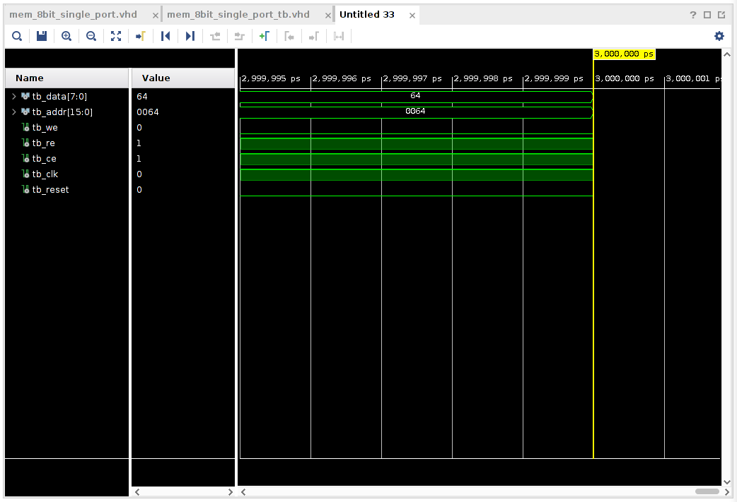
To run the testbench, click on Run Simulation under Simulation in the Flow Navigator and select Run Behavioral simulation· Vivado will work for a while but should then present something looking like the picture below in the right side of the GUI.
 .
.
Note do not forget to go into the settings first and setting a sensible time duration for the simulation. Look here.
| Zoom in at beginning of writes | zoom in at beginning of reads |
|---|---|
 |
 |
This was fun. No idea if this is going to work as part of any larger system at the moment. We will figure that out over time. As usual I would love your feedback, hints, tips or just friendly interaction. If you can tell that I am going off in a very wrong direction, let me know, please.
Thanks for reading and have a good day!
Please contact me with questions, suggestions or feedback at blog (dot) joel (dot) svensson (at) gmail (dot) com or join the google group .
© Copyright 2020 Bo Joel Svensson
This page was generated using Pandoc.